|
Temperature range
|
-40 ℃~﹢80 ℃
|
|
Relative humidity range
|
5 %~95 %
|
|
Altitude range
|
-500 m~﹢4000 m
|
|
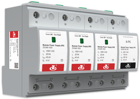
Model
|
ZGG40-1000(3+1)
|
|
SPD According to IEC 61643-11
|
Class Ⅱ
|
|
SPD According to EN 61643-11
|
Type 2
|
|
Max. continuous operating voltage UC
|
L-N: 1000 V AC; N-PE: 255 V AC
|
|
Nominal discharge current In (8/20 μs)
|
L-N: 20 kA; N-PE: 100 kA
|
|
Max. discharge current Imax (8/20 μs)
|
L-N: 40 kA; N-PE: 160 kA
|
|
Voltage protection level Up
|
L-N: 4 kV; N-PE: 2.5 kV; L-PE: 5.5 kV
|
|
Max. backup fuse
|
80 A gL/gG
|
|
Leakage current
|
≤ 20 μA
|
|
Connection mode
|
Parallel
|
|
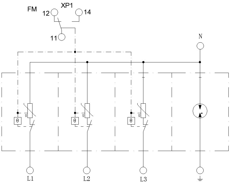
Protection mode
|
L-PE
|
|
Response time tA
|
≤ 100 ns
|
|
Cross-sectional Area
|
Stranded: 1.5 mm2 ~ 25 mm2
Solid: 1.5 mm2 ~ 35 mm2 |
|
Max. Cross-sectional Area For
Remote signalling terminals |
1.5 mm2
|
|
Switching capacity of remote signalling alarm contacts
|
AC: 250 V/0.5 A 125 V/1 A DC: 30 V/0.1 A
|
|
Torque: Connecting Terminal/Remote Signalling Interface
|
2.5 N•m /0.25 N•m
|
|
Degree of Protection (IP Code)
|
IP 20
|
|
Installation system
|
TN、TT、IT
|
|
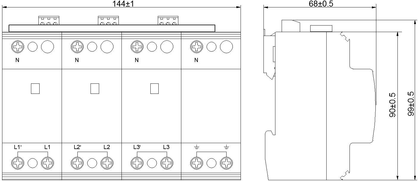
Installation system
|
90 mm×144 mm×68 mm
(excluding remote signalling terminals) |
|
Dimensions
|
DIN 35 mm rail
|
|
Mounting on
|
UL94 V-0
|