

|
Temperature
|
-40℃~85℃
|
|
Relative humidity
|
5 %~95 %
|
|
Altitude
|
-500 m~﹢4000 m
|
|
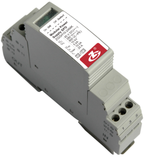
Model
|
ZGGH10-24
|
|
SPD According to IEC 61643-1
|
Class Ⅱ, Class Ⅲ
|
|
SPD According to EN 61643-11
|
Type 2, Type 3
|
|
Max. continuous operating voltage Uc
|
+— -: 45 V DC; - — PE: 0 V
|
|
Nominal discharge current In (8/20 μs)
|
5 kA
|
|
Max. discharge current Imax (8/20 μs)
|
10 kA
|
|
voltage protection Up
|
+ — -: 280 V; - — PE: 800 V
|
|
Compound wave Uoc
|
10 kV
|
|
Rated load current IL
|
25 A
|
|
Prepositioned fuse
|
25 A gL/gG
|
|
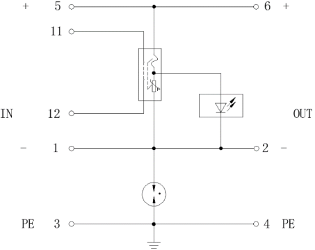
Connection mode
|
Series; Parallel
|
|
Protection mode
|
+ — -; - — PE
|
|
Response time tA
|
+ — -: ≤ 25 ns; - — PE: ≤ 100 ns
|
|
Cross-sectional area of connecting terminals
|
Multicore: 0.2 mm2~2.5 mm2
Single-core: 0.2 mm2~4 mm2 |
|
Cross-sectional area of the remote signalling interface (max.)
|
2.5 mm2
|
|
Switching capacity of remote signalling alarm contacts
|
AC: 250 V/0.75 A 125 V/3 A DC: 30 V/2 A
|
|
Torque: connecting terminal
|
0.5 N•m
|
|
Enclosure degree of protection (IP code)
|
IP 20
|
|
Installation system
|
DC system
|
|
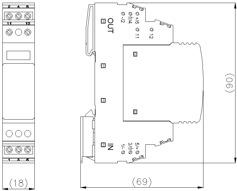
Dimensions
|
90 mm×18 mm×69 mm
(excluding remote signalling terminals) |
|
Mounting on
|
DIN 35 mm rail
|
|
Flammability
|
UL 94 V-0
|