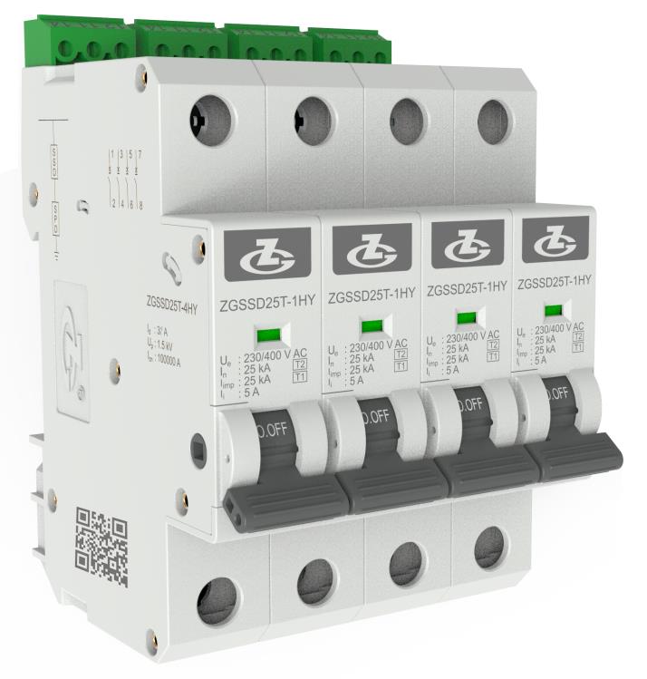
| Model |
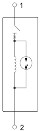
ZGSSD25T-1HY |
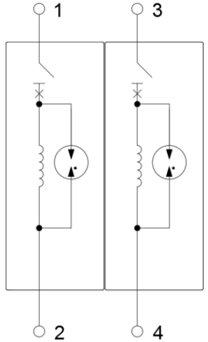
ZGSSD25T-2HY |
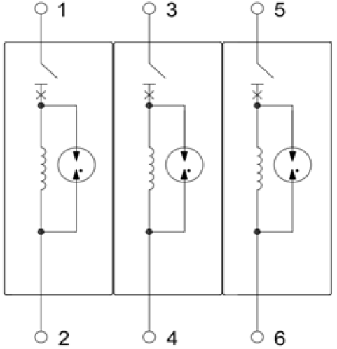
ZGSSD25T-3HY |
ZGSSD25T-4HY |
| SSD according to NB/T 42150 |
Class Ⅰ, Class Ⅱ |
| Rated operating voltage Ue |
230/400 V AC |
| Working frequency |
50/60 Hz |
| Rated insulation resistance Ui |
690 V AC |
| Nominal discharge current In (8/20 μs) |
25 kA |
| Impulse discharge current Iimp (10/350 μs) |
25 kA |
| Voltage protection level Up |
1.5 kV |
| Minimum instantaneous operating current Ii |
5 A |
| Minimum delay operating current Id |
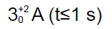 |
| Rated short circuit capacity Icn |
100 kA |
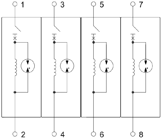
| Pole number |
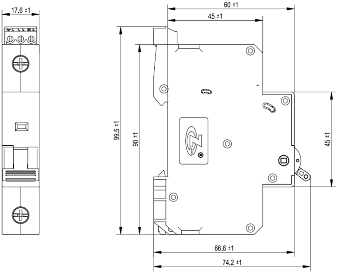
1P |
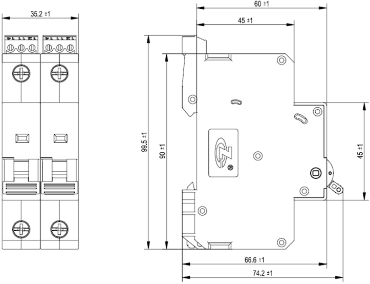
2P |
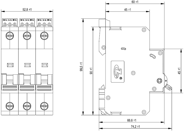
3P |
4P |
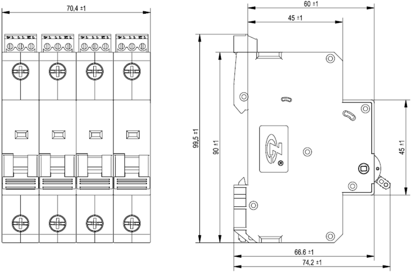
| Cross-sectional area of the copper wire connected by the terminal |
Flexible wire: 1.5 mm2~25 mm2, rigid wire: 1.5 mm2~35 mm2 |
| Cross-sectional area of the copper wire connected by remote signaling terminal |
0.5 mm2~1.5 mm2 |
| Switching capacity of remote signalling alarm contacts |
AC: 250 V/0.5 A, 125 V/1 A; DC: 30 V/0.1 A |
| Torque: Terminal/Remote signaling interface |
2.5 N•m /0.25 N•m |
| Application system |
TN, TT |
| Installation mode |
35 mm DIN rail (Type TH 35, according to IEC/EN 60715) |
| Dimensions: |
90 mm×17.6 mm×74.2 mm (excluding remote signaling terminal) |
90 mm×35.2 mm×74.2 mm (excluding remote signaling terminal) |
90 mm×52.8 mm×74.2 mm (excluding remote signaling terminal) |
90 mm×70.4 mm×74.2 mm (excluding remote signaling terminal) |
| Degrees of protection of enclosure |
IP20 |
| Housing flammability |
UL 94 V-0 |