

|
Temperature
|
-40℃~85℃
|
|
Relative humidity
|
5 %~95 %
|
|
altitude
|
-500 m~﹢4000 m
|
|
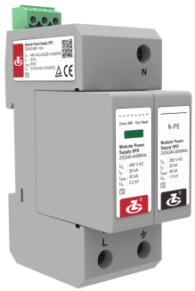
Model
|
ZGG40-75(1+1)hs
|
ZGG40-275(1+1)hs
|
ZGG40-320(1+1)hs
|
ZGG40-385(1+1)hs
|
ZGG40-440(1+1)hs
|
|
SPD according to IEC 61643-11
|
Class Ⅰ and Class Ⅱ
|
Class Ⅱ
|
Class Ⅱ
|
Class Ⅱ
|
Class Ⅱ
|
|
SPD according to EN 61643-11
|
Type 1 and Type 2
|
Type 2
|
Type 2
|
Type 2
|
Type 2
|
|
Max. continuous operating voltage UC
|
L-N: 75 V AC,100 V DC
N-PE: 150 V AC |
L-N:275 V AC
N-PE:260 V AC |
L-N:320 V AC
N-PE:260 V AC |
L-N:385 V AC
N-PE:260 V AC |
L-N:440 V AC
N-PE:260 V AC |
|
Operating frequency
|
-
|
50/60 Hz
|
50/60 Hz
|
50/60 Hz
|
50/60 Hz
|
|
Nominal discharge current
In (8/20 μs) |
L-N:15 kA
N-PE:20 kA |
20 kA
|
20 kA
|
20 kA
|
20 kA
|
|
Max. discharge current
Imax (8/20 μs) |
40 kA
|
||||
|
Impulse current Iimp(10/350 μs)
|
L-N:4 kA
|
-
|
-
|
-
|
-
|
|
Voltage protection level Up
|
L-N:0.65 kV
N-PE:1 kV |
L-N:1.4 kV
N-PE:1.5 kV |
L-N:1.6 kV
N-PE:1.5 kV |
L-N:1.8 kV
N-PE:1.5 kV |
L-N:2.2 kV
N-PE:1.5 kV |
|
Follow Current Interrupting Rating Ifi
|
N-PE: 100 Arms
|
||||
|
Max. backup fuse
|
63 A gL/gG
|
80 A gL/gG
|
80 A gL/gG
|
80 A gL/gG
|
80 A gL/gG
|
|
Connection mode
|
parallel
|
||||
|
Protection mode
|
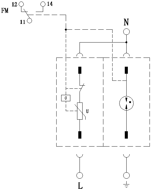
L(+)-N(-), N(-)-PE
|
L-N、N-PE
|
L-N、N-PE
|
L-N、N-PE
|
L-N、N-PE
|
|
Response time tA
|
L-N: ≤ 25 ns; N-PE: ≤ 100 ns
|
||||
|
Cross-sectional Area
|
Stranded: 1.5 mm2~25 mm2, Solid: 1.5 mm2~35 mm2
|
||||
|
Max. Cross-sectional Area For Remote signalling terminals
|
1.5 mm2
|
||||
|
Switching capacity of remote signalling alarm contacts
|
AC: 250 V/0.5 A 125 V/1 A DC: 30 V/0.1 A
|
||||
|
Torque: Connecting Terminal/Remote Signalling Interface
|
2.5 N•m /0.25 N•m
|
||||
|
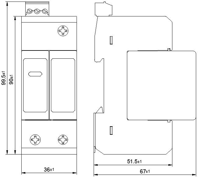
Degree of Protection (IP Code)
|
IP 20
|
||||
|
Installation system
|
TN、TT
|
TT、TN
|
TT、TN
|
TT、TN
|
TT、TN、IT
|
|
Mounting on
|
DIN 35 mm rail
|
||||
|
Flammability
|
UL 94 V-0
|
||||